9.2. Setting up the Electronics
In this section, the reader will be given a schematic of the circuit the rest of this guide will assume. In order to set it up, the user must acquire at least the following:
Wiener VM-USB controller
CAEN V775 time-to-digital converter
CAEN V785 peak-sensing analog-to-digital converter
Struck SIS3820 32-channel scaler
Gate and delay generator
Delay module
Constant-fraction discriminator
Plenty of lemo cables
Ribbon cable or a handful of twisted pair cables
ECL-to-NIM converter
Pulser
VME crate
NIM crate
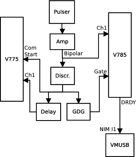
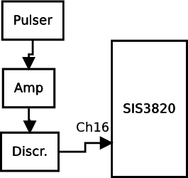
Rather than detail how to plug each cable into each module, th electronics diagram for the digitizers is provided in Block diagram of the V775 and V785 wiring. Take note that this is a very basic circuit that makes no attempt to handle busy logic properly. It is designed specifically for generating some test data. Be aware also that there are some signal conversions not shown in the block diagram because their need depends on the exact hardware being used. It is left up to the reader to determine whether a logic signal needs to be converted from ECL to NIM or ECL to TTL or whatever between modules. A separate diagram is provided for the the scaler portion of the circuit at Block diagram of SIS3820 scaler wiring.