12.4. Configuration menu
To provide some extra configuration control of the device, there are a few specialized configuration dialogs that can be reached from the "Configure" drop down menu. They are described here.
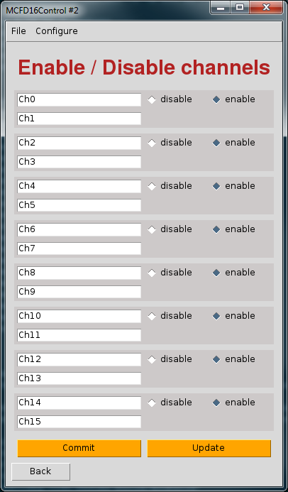
12.4.1. Enable/Disable Channel
The output for channels can be disabled in the MCFD-16. Support for this feature is provided through the dialog at "Configure > Enable/disable..." It is important to realize that enabling and disabling a channel is done for channel pairs rather than individual channels. The same semantics apply to this dialog for committing settings to the module as for the rest of the application. You must press "Commit" to transfer the state of the GUI to the module. You can read the state of the module by pressing the "Update" button. Each commit operation is always followed by an update operation intrinsically so that you can see whether a change succeeded or failed.
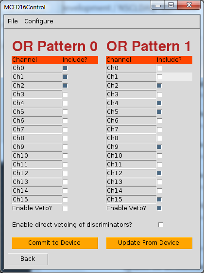
12.4.2. Configurable 16-Channel OR Trigger
The MCFD-16 provides 3 trigger outputs that can be defined to emit signals defined by various logic internal to the device. NSCLDAQ supports setting two of these [trigger 0 (front panel output) and trigger 1 (back panel output)] to emit a configurable 16-channel OR. Each of these is configurable through the "Configure > Trigger OR..." menu. In the dialog, there are two columns labeled "OR Pattern 0" and "OR Pattern 1". The OR Pattern 0 column configures the output for trigger 0 and the OR Pattern 1 column configures the output for trigger 1. The same semantics hold for causing a change to the device as for the rest of the MCFD16Control application. Changes to the GUI are not applied to the device until the "Commit to Device" button is pressed. If you want to update the GUI to reflect the state of the module, you should press the "Update From Device" button. Note that when you press "Commit to Device", the GUI will automatically follow the writes to the module with a read. The read does the same thing as when you press "Update From Device".
Another control accessible from this dialog is the ability to enable and disable the direct vetoing of the discriminators. This is referred to as the fast veto in the manual. Enabling this applies the veto to the discriminator stage of the module, which is before it reaches the logic for the trigger decision. It has been observed that if the veto associated with the OR pattern is disabled and the fast veto is enabled, there might still be some triggers when the input signal has a very fast rise time and the bandwidth limit setting is not enabled. The triggers are caused by nonlinearities in the amplfication stage of the MCFD-16. The moral of the story is that if you want to ensure that the trigger is not outputted when a veto is present, then you should not rely on the fast veto being enabled. Rather you should select the veto setting for the OR pattern you are concerned with.