OPTIONS
- -slot value
Specifies the slot of the CAMAC crate the target module is occupying. Default is 1.
- -firmware path
The path to the firmware file usbtrig.bit. Default is "" making this a mandatory parameter.
- -readRegister bool
Specifies whether to add a hit register read into the event stack. Defaults to true.
- -eventwiseClear bool
Specifies whether to send a clear command via the CAMAC dataway at the end of the event. Defaults to true.
- -forceFirmwareLoad bool
By default, the ULM will only load the firmware if it fails to validate the configuration. This occurs always after a bad firmware load or after a crate has been power cycled. Firmware loads take a bit of time so it is worthwhile to skip reloading the firmware on every run. However, sometimes it may be considered useful. This option causes the firmware to be loaded at the start of EVERY run. Defaults to false.
- -configuration num
Specifies the number that will be used to validate a successful firmware configuration. This number is compared to the value returned by the function A=15 F=0. Default is 0
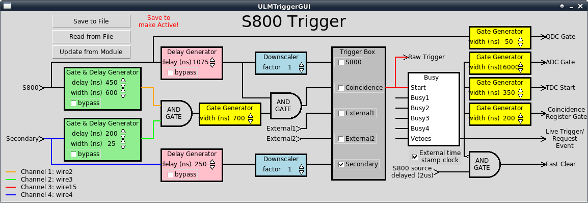
The next set of parameters allow the user to intialize the trigger parameters. These are best understood by referencing a picture of the ULM trigger GUI. See below:
- -pcDelay num
Primary S800 Gate and delay generator delay value in units of 25ns. This is for the green box at the left of the top branch of the trigger logic. Default is 0.
- -pcWidth num
Primary S800 Gate and delay generator width value in units of 25 ns. This is for the green box at the left of the top branch of the trigger logic. Default is 0.
- -scDelay num
Secondary gate and delay generator delay value in 25ns units. This is for the green box to the left of the bottom branch of the trigger logic. Default is 0.
- -scWidth num
Secondary gate and delay generator width in 25ns units. This is for the green box to the left of the bottom branch of the trigger logic. Default is 0.
- -psDelay
Delay length in units of 25ns for the delay generator (pink box) in the primary trigger branch of the logic. Default is 0.
- -ccWidth num
Width of the coincidence gate (yellow box after the AND in the middle of the trigger logic) in 25ns units. Default is 0.
- -ssDelay num
Length of delay in 25ns units for the delay generator in the secondary trigger. This is the pink box at the bottom of the trigger GUI. Default is 0.
- -bypasses num
Bitmask of bypasses (check boxes on various elements of the trigger logic). Default is 0.
- -pdFactor num
S800 downscale value (the blue box at the top middle of the trigger GUI). Default is 0.
- -sdFactor num
Secondary trigger scaledown value (the blue box at the bottom middle of the trigger GUI). Default is 0.
- -triggerBox num
Bit mask for the check boxes in the Trigger Box. Default is 0.
- -inspect1 num
Selects the wire number routed to the inpect 1 output. Default is 0.
- -inspect2 num
Selects the wire number routed to the inspect 2 output. Default is 0.
- -inspect3 num
Selects the wire number routed to the inspect 3 output. Default is 0.
- -inspect4 num
Selects the wire number routed to the inspect 4 output. Default is 0.
- -adcWidth num
Selects the width of the output from the ADC Gate generator (see the yellow boxes to the right of the trigger GUI). Units are 25ns. Default is 0.
- -qdcWidth num
Sets the width (in 25 ns units) of the gate generator for the QDC. See the yellow boxes at the right of the trigger GUI. Default is 0.
- -tdcWidth num
Sets the width of the TDC gate generator in 25ns units. See the yellow boxes at the right of the trigger GUI. Default is 0.
- -coincWidth num
Sets the width of the coincidence gate generator in 25ns units. Default is 0.