11.2. The electronics
The CAEN V785 is a 12-bit, 32-channel analog-to-digital converter that returns a digitized value of the maximum voltage that occurs during the time a gate is present. The input signal must be positive and less than 4V. The V785 is a VME-based module. For a complete understanding of the module I suggest that you obtain a copy of the product manual, available as a PDF at http://www.caen.it/.
The CAEN V262 is a device that can perform basic functions when an input signal is received. For this setup, a register on the device will be polled by software to determine if a signal is present. You can also find the product manual for this by visiting the manufacturer's website at http://www.caen.it/.
11.2.1. A minimal electronics setup
The following items will be needed to build our simple setup:
CAEN V785 ADC module
VME Crate
SBS Bit3 PCI/VME bus interface
NIM Crate
NIM Spectroscopy amplifier of some sort
NIM Discriminator
Two channels of NIM Gate and delay generator
NIM Signal splitter
LEMO to Ribbon cable converter
Pulser
50-Ohm LEMO terminator
An assortment of LEMO cables
A 34-conductor ribbon cable with 3M connectors on each end
An oscilloscope
A CAEN V262 IO Register
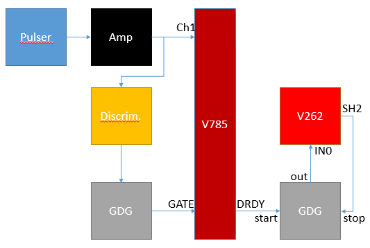
Before starting, be sure that you can secure all of these items, many are available through the NSCL electronics pool. Figure 1-1 shows the complete setup of the system, due to the varying amount of familiarity of readers to the electronics, a brief description of the component and what the signal coming out of it should look like will be given.
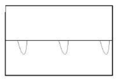
We will first look at the signal from the pulser. A pocket will work well for this. A pocket pulser will give a small negative pulse, but we will invert it later. The signal directly from the pulser will look like figure 1-2 when viewed on a scope. The pulser only works when terminated with 50 Ohms.
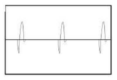
The pulser will run directly into a NIM based amplifier. This amplifer serves two purposes. First it will amplify our signal helping it stand out against any noise we might have in the channel. It will also invert the negative pulser signal giving us the positive signal that is required by the V785. The signal coming from the bi-polar output of the amplifier will look like figure 1-3. Adjust the gain on the amplifier until you output signal has an amplitude of about 2V
After you are happy with the signal from the amplifier, plug the bipolar output into the splitter. The splitter will simply split the signal much like a "T" but will keep the 50 Ohm termination needed by the pulser.
Take an output of the splitter, convert it to a ribbon cable, and plug that into the channel inputs of the V785. Ribbon cable can be difficult to work with because it is easy to get it twisted and lose track of which end is which. To avoid this look carefully at the coloring on the cable you are using and be sure it is plugged into the correct channel of the ADC. Another useful tip is that the connectors typically have a marking on one end to conventionally identify channel 0.
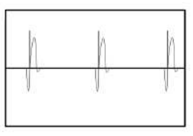
The other output from the splitter will go into a discriminator. This could be either a leading edge or a constant fraction discriminator. The job of the discriminator is to output a logic signal when an input signals has exceeded a certain voltage threshold. The output signal will be used to tell the ADC to initiate the process of recording the peak height of the signal. The discriminator will have a threshold knob, be sure that the threshold is set above any background noise that may be present so that the discriminator only trips on the pulser signal. It will be useful to look at the both the logic pulse and the signal from the amplifier at the same time when setting the threshold value. Figure 1-4 shows what you will see.
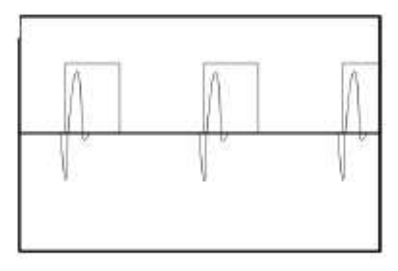
When the threshold is set to a reasonable level, connect one of the discriminator outputs to the start of one channel of your gate and delay generator. The gate and delay generator will generate a gate when it receives a logic signal from the discriminator. When looking at the signal from the amplifier and the gate at the same time on the scope, the signal pulse should fall within the gate as seen in figure 1-5. If the gate is occurring too early you can use the gate and delay generator to delay the gate or to make the gate last longer. If the gate is too late you need to delay the signal pulse, that can be done using a delay module, or by adding cable delay. When you are happy with the gate timing, plug it into one of the LEMO connectors on the CAEN V785 labeled gate, put a 50 Ohm terminator in the other one.
Next we will take the "DRDY" output of the V785 and send that into the start input of a gate delay generator. We will then take the output of that gate delay generator into the IN0 of the CAEN V262. Next you should connect the SHP2 output of the V262 to the stop input of the GDG. This scheme ensures that the signal at INO is held high long enough for the software to recognize it.
At this point your setup should be complete. Now is good time to make sure that your setup is the same as Figure 1-1. If everything is setup correctly the BUSY and DRDY lights on the V785 should be lit up when we start actually taking data in subsequent sections of this tutorial.
