10.2. Setting up the Electronics.
A minimal electronics setup will need to:
Provide a start signal to the TDC
Provide a stop signal to the TDC. For this setup we will use a delayed start signal.
In this simple setup we will trigger the computer readout when data are ready in the TDC. Since we only have a single module, its busy output also indicates when the system as a whole is busy.
The electronics diagram below lets us use a simple pocket pulser to run this system:
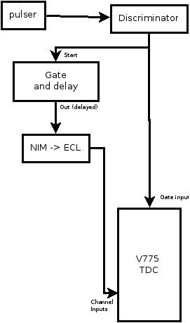
The discriminator creates a digital pulse from the analog pulser signals. One discriminator output is fed to the Gate NIM input of the TDC and will serve as the TDC start signal. A second output is delayed by the Gate and delay generator before being converted to the differential ECL signal expected on the ribbon cable inputs of the V775.
When you connect the ribbon cable between the V775 and NIM->ECL converter, be careful the read the module front panels to ensure that pin 1 on the NIM-> ECL converter goes to pin 1 on the TDC.