|
NSCL DDAS
1.0
Support for XIA DDAS at the NSCL
|
|
NSCL DDAS
1.0
Support for XIA DDAS at the NSCL
|
One of the complications that surrounds digital systems is that a lot of the configuration parameters are internal to the device. In the "old days", the parameters to process analog signals emitted from detectors were set by turning knobs on devices such as spectroscopy amplifiers, timing filter amplifiers, discriminators, etc. These knobs could be adjusted and the effect on the signal easily observed on an oscilloscope. Modern digitizers do not behave this way because all of the signal processing has been internalized inside the digitizer. For that reason, software is needed to pass parameters to the device and then also to see the effects of the parameters. Nscope provides provides just these functionalities for the XIA Pixie-16 digitizer family that composes the Digital Data Acquisition System (DDAS).
In the following user guide, we will cover
Nscope provides a number of useful features for configuring the device and also for testing configurations. Those features are:
Nscope is an essential tool for running a DDAS system because it is the only mechanism provided to configure these devices.
The very first thing that a user needs to do to run nscope is to connect a PXI crate with at least one Pixie-16 card to a host pc. The PXI crate must be powered on.
The next step is to choose the version of the DDAS that you will be using. The installation directory of DDAS at the NSCL is in the /usr/opt/ddas. In this directory there will be at least one version available for use. Choose the version you want to run and then source its ddassetup.bash script. For example, if you are going to use version 1.0-001, then you must execute the following command :
source /usr/opt/ddas/1.0-001/ddassetup.bash
This script defines and exports the DDAS_ROOT, DDAS_BIN, DDASLIB, DDAS_INC, and DDAS_SHARE environment variables.
The next step in setting up nscope is the creation of a cfgPixie16.txt file. This file is a simple text file that contains the location of the Pixie-16 cards in the crate. The nscope program reads this file at start up and it must therefore exist prior to running nscope. The cfgPixie16.txt file has the basic general structure:
Crate Id (not used)
Number of modules in crate
Slot of 1st module
Slot of 2nd module
...
Slot of Nth module
Path to parameter file (.set)

# the remaining sections are optional
[100MSPS]
Path to FPGA firmware file
Path to fippi firmware file
Path to dsp firmware file
Path to dsp parameter file
[250MSPS]
Path to FPGA firmware file
Path to fippi firmware file
Path to dsp firmware file
Path to dsp parameter file
[500MSPS]
Path to FPGA firmware file
Path to fippi firmware file
Path to dsp firmware file
Path to dsp parameter file
To be more illustrative, consider a DDAS system with two Pixie-16 modules. One module resides in slot 2 and the other in slot 4. Furthermore, the settings file that will be used is located at /path/to/my/params.set. The cfgPixie16.txt file for such a setup would look like:
1                       # crate id
2                       # number of cards
2                       # slot of first card
4                       # slot of second card
/path/to/my/params.set  # path to params
The human-readable notes at the end of each line are actually allowed in the file, because all characters after the first whitespace character in each line are ignored. If this is the first time that you have set up a DDAS system and you have no preexisting parameter settings file, then you can find one at $DDAS_SHARE/crate_1.set.
Once the cfgPixie16.txt file has been suitably defined, then you can launch nscope by entering the following at the command line.
$DDAS_BIN/nscope
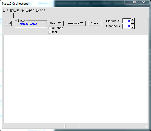
A window that looks like the screenshot at the top of the page should become visible on the screen. During the startup of nscope, there will be a bit of a output written to the terminal that the program was launched from. It will mostly be the contents of the cfdPixie16.txt file.
Here is a sample output:
Reading Firmware Version file... DDASFirmwareVersions.txt
Found Firmware    #[FPGAFirmwarefiles]
test: ../firmware/syspixie16_revfgeneral_adc500mhz_rxxxxx.bin
Reading config file... cfgPixie16.txt

1 modules, in slots: 2

current working directory /user/0400x/nscope
This output should mirror the information that was found in the cfgPixie16.txt file. The first thing that needs to be done in nscope is to boot the Pixie-16 cards in the crate. During the boot process, the firmware is reloaded and the parameter configuration file is written to the modules in the crate. Once again, textual output will appear in the terminal to display information about the booting process. It will look something like this:
Reading Firmware Version file... DDASFirmwareVersions.txt
Found Firmware    #[FPGAFirmwarefiles]
test: ../firmware/syspixie16_revfgeneral_adc500mhz_rxxxxx.bin
Reading config file... cfgPixie16.txt

1 modules, in slots: 2

Booting all Pixie-16 modules...

Booting Pixie-16 module #0, Rev=12, S/N=184, Bits=12, MSPS=100
ComFPGAConfigFile:  /user/ddas/ddasDaq/standard/LucidXIA/test100/firmware/syspixie16.bin
SPFPGAConfigFile:   /user/ddas/ddasDaq/standard/LucidXIA/test100/firmware/fippixie16.bin
DSPCodeFile:        /user/ddas/ddasDaq/standard/LucidXIA/test100/dsp/Pixie16DSP.ldr
DSPVarFile:         /user/ddas/ddasDaq/standard/LucidXIA/test100/dsp/Pixie16DSP.var
--------------------------------------------------------

Start to boot Communication FPGA in module 0
Start to boot signal processing FPGA in module 0
Start to boot DSP in module 0
Boot all modules ok
DSPParFile:        /user/ddas/ddasDaq/standard/e09055_final/readout/crate_1/e09055.set
The information printed to the terminal should match the information that you provided in the cfgPixie16.txt file.
Each card needs to be booted sequentially so this can take some time. The amount of time required to boot the system will increase as the number of modules in the crate increases. As soon as the system completes the boot process, the status indicator next to the boot button will change to state that the system is booted.
In this section, the various dialogs in the "UV_Setup" drop-down menu will be detailed. These dialogs allow the user to set up the various parameters for each device in a crate. Changes made to these parameters will produce visible changes to the way the device triggers and computes energy information for a given signal. The next section will describe how to use Nscope to perform a histogramming run and view the results.
Before attempting to configure the energy filter, it would be prudent to read through the Pixie-16 manual because it will provide lots of details concerning the filter detail the concept of the trapezoidal filter and how it is used to generate a trigger and energy value from an input signal. The following sections will describe how to configure the parameters that control these filters.
There are a lot of similarities between many of the dialogs in nscope. In this section, a few of these features will be described to avoid repetition throughout the manual.
The dialogs provide direct access to parameters. It should be understood that the dialogs are designed to interact with the module on an as needed basis. Changes that are made to the dialogs are not written to the device until the user presses the "Apply" button. If the user wants to be read the parameters from the module, then he/she should press the "Load" button. The load button "loads" the value from the device into the dialog. Dismissing a dialog is accomplished by pressing the "Cancel" button. There is not interaction made with the associated Pixie-16 card when the cancel button is pressed.
Nscope refers to modules in a crate by a module index. This index is assigned based on the order of the module from left to right. The leftmost module is assigned index 0 and then subsequent modules to the right are assigned incrementally larger indices.
Most dialogs in nscope consist of a table of editable text entries and often the rows in these tables correspond to channels. That means that there are usually 16 rows in a given dialog to edit. Many times the user will want to set the same parameter values for all channels and a convenient copy mechanism exists to facilitate it. Dialogs that support copying will have a "Copy" button. When the copy button is pressed, the parameters of a single row are copied into the respective cells of the other channels. The source of the parameters to copy correspond to the channel number in the spinbox labeled "Select channel #".
Signals that are input to the Pixie-16 digitizers are first processed as analog signals prior to digitization. There are three parameters per channel that can be set to control the analog conditioning and they are controlled via a dialog launched from the UV_Setup > Analog Signal Conditioning drop-down menu.
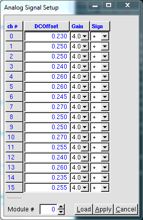
The Pixie-16 digitizers apply a DC offset to the analog signal, amplification, and a possible inversion of the signal. The dialog provides control over all three the aspects of the analog conditioning circuit. The parameter in the column labeled "DCOffset" will control the DC offset, the "Gain" column will control the amplification, and the polarity is controlled by the "Sign" column. The user should set the value of sign to the actual polarity of the input signal.
The settings for the 16 channels of a single module are displayed at a single time. To configure a module that is different than currently visible, use the "Module #" spinbox. This spinbox identifies a module based on its index. The leftmost module in the crate is module 0 and each subsequent module to the right of it is assigned incrementally higher module numbers.
The energy filter can be configured with the energy filter dialog found in the drop-down menu at UV_Setup > Energy Filter. The following dialog will pop up:
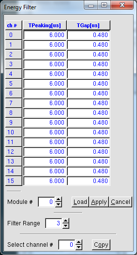
The energy filter is configured by three parameters: the peaking time (TPeaking), the gap time (TGap), and the filter range. The TPeaking time corresponds to the "Length" in the manual and the gap time corresponds to the "Gap" in the manual. The filter range is a parameter that allows the user to implement longer filters. The first two parameters are laid out in a table with each row representing a channel and each column representing a parameter. At any given time, only one module's parameters are visible. You can use the spin box labeled "Module #" at the bottom of the dialog to select which device is being configured.
To configure the basic triggering characteristics of each channel, the user should use the trigger filter dialog. It is reachable through the drop-down menu at the top of the screen as UV_Setup > Trigger Filter. The dialog provides controls over the peaking time (TPeaking) and the gap time (TGap) that define the trigger filter. These parameters are used for generating the fast trigger. The rightmost column "Thresh." defines the threshold setting for the device. When the CFD triggering is disabled ( see The CSRA dialog ), the threshold is used with the trigger filter output to implement a leading-edge discriminator. Once the output of the trigger filter exceeds the threshold, a fast trigger is generated.
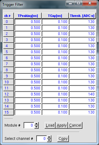
Alternatively, if the CFD is enabled then the peaking and gap times are used in conjunction with the scale and delay factors to implement a CFD algorithm. If the CFD output fails to exceed the CFD threshold, the trigger filter threshold will be used instead to generate a fast trigger.
The user can configure the device to use a digital CFD algorithm for triggering and timestamping. The CFD algorithm makes it possible to get timestamps with better resolution than the ADC clock. Enabling usage of the CFD must be done in the CSRA configuration dialog. It is launched from the UV_Setup > CFD drop-down menu.
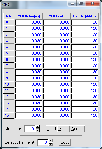
The CFD algorithm requires three parameter settings to control, and they are the delay, scale, and threshold. Each of these can be configured channel-wise in the dialog.
The CFD implementation used by the Pixie-16 digitizers is described in detail in the manual. It will not be repeated here. The manual is silent, however, on the logic surrounding when the CFD is in use. Here we will describe more of the practical details associated with the CFD algorithm.
The user can enable or disable use of the CFD algorithm in the CSRA register. If CFD mode is disabled, then the algorithm is never used and the user will get no extra CFD timing information in the data structure. Instead, the fast trigger will be generated when the trigger filter exceeds its associated threshold, see nscope_triggerDialog_sec. Furthermore, the resolution of the timestamp assigned to each event will be limited to the resolution of the FPGA clock. For the 250 MSPS and 500 MSPS boards, that implies that the timestamp will be assigned with a 125 MHz clock rather than a 250 MHz or 500 MHz clock.
When CFD mode is enabled, the CFD algorithm only creates the fast trigger and CFD timing if the positive portion of the CFD filter exceeds the user defined threshold. When the threshold is exceeded, the CFD algorithm will compute a 16-bit correction, i.e. the CFD time, to the 48-bit timestamp. The meanings of the bits in the CFD time differ with the hardware revision. The table below describes how to interpret their meaning as a function of the hardware revision:
| Revision | Sampling Rate (MSPS) | Bit Meanings | ||||||||
|---|---|---|---|---|---|---|---|---|---|---|
| B/C/D | 100 |
| ||||||||
| F | 250 |
| ||||||||
| F | 500 |
|
If, on the other hand, the threshold is not exceeded, then the CFD algorithm is not used and a CFD time is not generated. The module effectively behaves as though the CFD were disabled for that event. That fallback mechanism only lasts for the current event, so that the next event is evaluated in CFD mode again.
As with any digitizers, the Pixie-16 modules can be configured to output the raw digital waveforms (a.k.a. traces) that were generated by the flash ADCs. To enable the acquisition of the waveforms, the user must use the CSRA dialog (see The CSRA dialog). The actual parameters that control how the waveforms are acquired are controlled using the pulse shape dialog. It can be found in the UV_Setup > Pulse Shape drop-down menu.
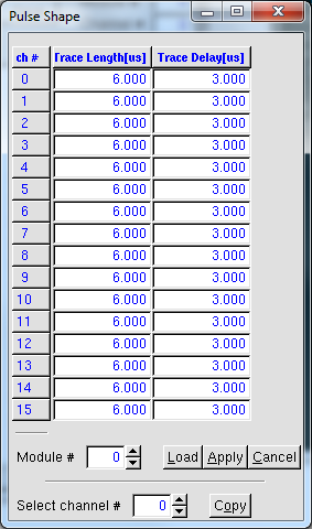
The two parameters that control the characteristics of waveform acquisition are the length of the waveform (Trace Length) and the delay (Trace Delay). The user can edit the entries of each parameter individually.
A trapezoidal filter in its simplest form will operate optimally on a step function. The signals that are input into the Pixie-16 digitizers, however, are not step functions. They fall back to baseline levels. The decay time parameter is used to compensate for this falling edge when computing the energy and is therefore important to the energy resolution. The user can set this parameter manually through the UV_Setup > Decay time drop-down menu.
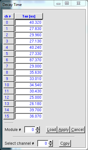
Normally, the user would not manually enter the In normal usage, the user would probably be more interested to use nscope's built in algorithm for computing the decay time automatically. The user can use this feature by clicking on the Expert > Find tau drop-down menu.
There is a two stage trigger used by the Pixie-16 devices to determine when an input signal will produce data to be read out. The first stage is associated with the trigger filter or CFD filter parameters and will generate a fast trigger. The fast trigger exists inside the module, but the user can gain access to it for channel 0 through the LVTTL outputs on the front panel. The second stage, or validation stage, checks that the fast trigger is in coincidence with some other set of signals determined by the validation criteria. Validation criteria is set in the CSRA and CSRB dialogs. The user can choose to validate the fast trigger with an external gate, a coincidence criteria, or by an internally generated gate. If the fast trigger is validated, the data associated with it is kept for readout. Otherwise, the data is discarded.
A fast trigger is validated by being coincident with at least one other validation signal. To modify the relative timing of the fast trigger with the other signal it is to be in coincidence with, there are a set of timing parameters that can manipulated. Nscope provides controls over these through the timing dialog found at UV_Setup > Timing Controls.
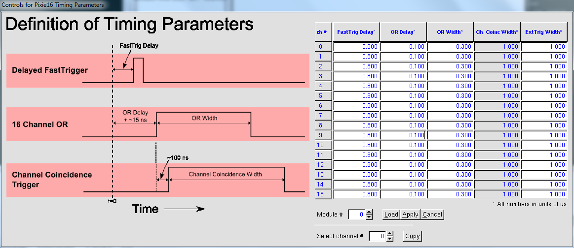
Within this window, the user is given control over three of the four parameters associated with timing in the Pixie-16 module. To clarify what these parameters actually perform, a diagram on the left is included to make the meanings of each parameter in the table explicit. The first three columns differ from the fourth for a couple of reasons based on controllability. The first reason is just that; they are controllable. Their values can be altered and subsequently written to the Pixie-16 module. To be clear, the values are not written to the module unless the [Apply] button is pressed. When this button is pressed, two things happen in the following order:
The fourth column is slightly different than the first three columns in the table, because the user cannot set its values or write its values to the Pixie16 module. For this reason, its values will be updated regardless if the [Apply] button is pressed on the Timing Controls dialogue. It merely displays the most current information. The rationale behind this is straightforward to understand. For any value presented by this table, the value will be updated when the user presses the Apply button on the dialogue that provides the ability to set it. Because the Timing Controls dialogue disallows the user to set the values in the fourth column, the Apply button has no effect on it. Its values are updated by pressing the Apply button on the Multiplicity Coincidence dialogue or by selecting a different module number. A note should be made about the timing diagram presented to the user. It is an accurate simplification of timing. However, if absolute measurements of timing are to be done, the user should understand that the time between the t=0 line displayed on the dialogue and the input time is subject to change with the value of the FastTrig Delay. Below is a more complete timing diagram:
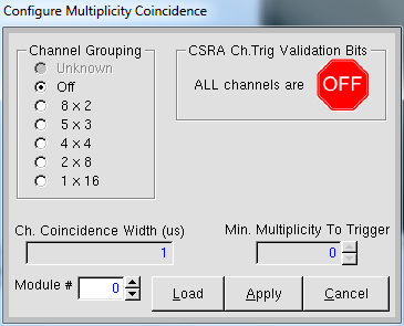
The components of the dialogue will be described in the following the section.
Six options are provided to the user to set the groupings of channels: 8x2, 5x3, 4x4, 2x8, and 1x16. The meaning of, for example, 8x2 is that there are eight groups of 2 channels. Such a setting would group channels (0,1), (2,3), (4,5), ... , and (14,15). The other groupings follow an analogous scheme, but the 5x3 is slightly different because it only groups 15 of the 16 available channels. In this scenario, the 16th channel is left to run in singles mode. The Unknown state will be set and the window highlighted in red (as shown above) if the settings read from the module are incompatible with functionality provided by this dialogue. IF THE DIALOGUE PRESENTS THE GREEN ON MESSAGE AND THE CHANNEL GROUPING IS SET TO UNKNOWN, THEN THE VALIDATION CONDITION IS UNDEFINED AND UNDEFINED BEHAVIOR WILL ENSUE.
This text input defines the Channel Coincidence Width that has been referenced already in the Timing Controls dialogue. It is here that the value can be changed and written to the module. The value set here is used to set all of the values identically for each channel.
The Multiplicity Coincidence dialogue controls the settings for the coincidence parameters but DOES NOT provide the ability to change the conditions for validation. As a result, the parameters defining the coincidence requirements can be written to the module without them actually be checked in the validation of events. If the user desires to require coincidences for validation of signals, the appropriate bits must be set in the CSRA dialogue. Because this is a potential source of confusion, the status of the CSRA bits is clearly displayed on the Multiplicity Coincidence dialogue. There are three states that the user might see: ON, OFF, and INCONSISTENT. Each state is described in
| Message | Description | Indicator |
|---|---|---|
| ALL channels are ON | Satisfaction of channel coincidences is required by every channel in the module. | 
|
| ALL channels are OFF | Satisfaction of channel coincidence settings is not required by every channel in the module. | 
|
| INCONSISTENT | Some channels require satisfaction of the coincidence settings while others do not. One should be careful to ensure that this is the desired configuration before proceeding. | 
|
The Pixie-16 modules have lots of features that can be enabled and disabled. An example that has been already mentioned is the CFD triggering. Disabling and enabling features is accomplished through the CSRA dialog, found at UV_Setup > CSRA. For the curious, CSRA is an acronym for "Control and Status Register A".
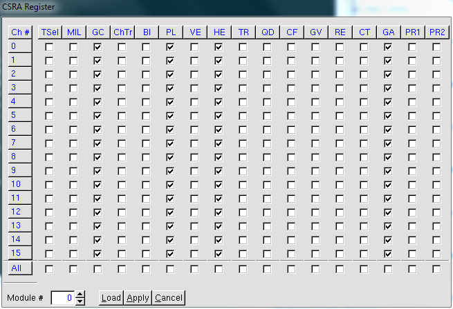
Though the CSRA dialog is a bit terse at first glance, looks are deceiving. Each of the headers to the columns provides more information when the cursor hovers over it. Each column represents a feature that can be enabled or disabled in a channel. The features are listed below in a table:
| Header | Meaning | Description |
|---|---|---|
| TSel | Fast trigger source | Unselected = use group trigger Selected = use external fast trigger |
| MIL | Module validation signal | Its meaning is not clear |
| GC | Enable channel validation | Unselected = disable channel validation, but fast triggers can still be generated Selected = enable validation |
| ChTr | Channel Validation Signal (Meaning not 100% clear, but only affects the 250 MSPS and 500 MSPS modules) | Unselected = local validation from system FPGA Selected = ChaneGate input from front panel |
| Bl | DAQ Blocking | Unselected = system never stop accepting triggers Selected = system rejects new input signals if trace or header DPMS are full |
| PL | Input signal polarity | Unselected = trigger on a negative signal Selected = trigger on a postive signal |
| VE | Enable/disable channel trigger veto | Unselected = disabled |
| HE | Histogram energy | Unselected = enable histogram energy Selected, disable histogram energy |
| TR | Enable/disable Trace capture | Unselected = disable Selected = enable |
| QD | Enable/disable QDC sums capture | Unselected = disable Selected = enable |
| CF | Enable/disable CFD triggering | Unselected = disable Selected = enable see The Pixie-16 CFD |
| GV | Global trigger validation | Unselected = do not require coincidence between global trigger and fast trigger Selected = require the coincidence |
| RE | Capture raw energies and baselines | Unselected = disable Selected = enable |
| CT | Channel trigger validation | Unselected = do not require channel multiplicity requirements to be satisfied Selected = channels in multiplicity mask must be in coincidence |
| GA | Gain setting | Unselected = set gain to 0.9 Selected = set gain to 4.0 |
| PR1 and PR2 | Pile up rejection | Both unselected = disable pile up rejection |
There is a second control and status register called CSRB. It is similar to CSRA in that it enables and disables options in the devices. It differs in the fact that it sets parameters that pertain to the entire module rather than to the individual channels. The CSRB dialog can be launched through the Expert > ModCsrb drop-down menu.
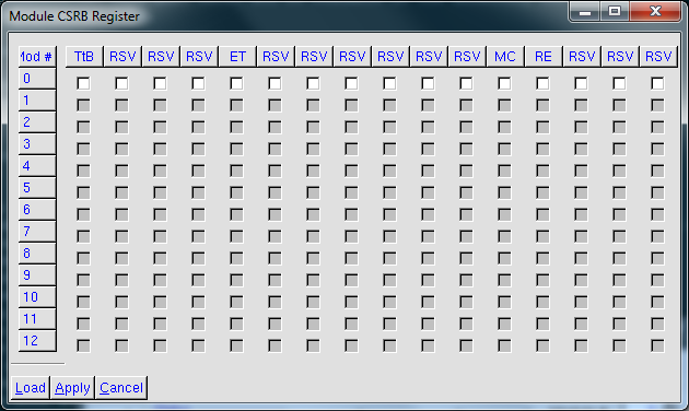
The CSRB dialog resembles the CSRA dialog significantly, but the rows represent modules rather than the channels. The rest of the rows are simply useless widgets. If the user hovers the cursor over the header of any of the columns, then a context label appears providing more information. The meaning of each of the columns is described here in more detail.
| Label | Meaning | Description |
|---|---|---|
| PUL | Enable pullups for backplane bus lines. ( This must be set for only one module in the crate! ) | Unselected = disabled Selected = enabled |
| DIR | Set as Director module | Unselected = module is not the director Selected = module is director |
| MAS | Set module as chassis (i.e. crate) master. (Only one module should have this selected per crate.) | Unselected = module is NOT chassis master Selected = module is chassis master |
| GFT | Select global fast trigger source (This feature is not yet understood) | Unselected = ?? Selected = ?? |
| ET | Select external trigger source | ?? Manual says "Enable this option to let this module accept external trigger and run inhibit signals and then put the signals on the backplane so that all modules can see the same signals. This should be enabled for only one module in the crate." but not sure that this is the same option. |
| INH | Enable use of external inhibit signal | Unselected = disable Selected = enable |
| MC | Distribute clock and triggers to multiple crates | Unselected = do not distribute Selected = distribute Needs to be set in ALL modules of a multicrate system |
| SOR | Sort events by timestamps | Unselected = disable Selected = enable |
| TTB | Enable connection of fast triggers to the backplane | Unselected = disable Selected = enable There are 2 buses per crate, so only 2 modules can set this bit per crate. This bit is requisite to inspect the fast triggers through the back plane breakout card. |
Let's be frank, the triggering capabilities of the Pixie-16 digitizers are many and that makes managing them downright complicated. A dialog for some trigger logic is is provided in the Expert > TrigConfig0 drop-down menu. If the user goes here, he/she is presented with the following window.
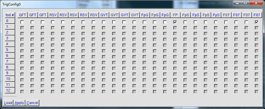
The most useful thing that the user is going to use this dialog for is to enable or disable the outputs on the front panel of a module. These outputs are useful for debugging and also outputting a triggering signal to the outside world if you are coupling DDAS with some other detector system. To enable or disable these signals you will have to select the "FP" bit for the desired module. If the bit is selected, it means that the module will output signals on the front panel. In order to use this feature, you are likely to need one of the DDAS LVTTL breakout boxes.
Once you have configured the module to suit your measurement, the settings will need to be saved to a .set file. The file that is saved will then be used later to configure the modules from within DDASReadout. To save the settings file,
From within nscope, there is currently no support to load a settings file. If you want to inspect an existing settings file, then you will need to:
In the previous section, the various dialogs to configure the parameters were described. It is left to discuss though how to determine whether the parameter set is useful or not. Nscope provides a number of facilities to determine this. There are two mechanisms for viewing the effects of parameters. The first is to acquire a trace and then analyze it. The second is to actually run the digitizers in histogramming mode and view the outputs. Each of these features will be described in the following sections.
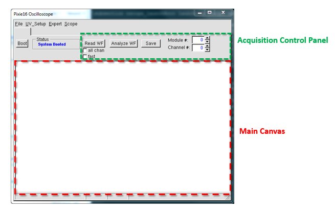
The default configuration of the main window displays a main ROOT canvas that will display traces and products of their analysis. There is also a control panel that allows the user to acquire and analyze a waveform. This panel provides the ability to select the module and channel that is being inspected. It also allows the user to manipulate how the acquisition occurs.
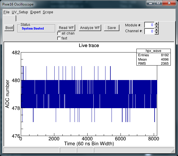
The "Read WF" button when pressed will acquire a trace from the module selected in the "Module #" spinbox. If the "all chan" checkbutton is left unchecked, then a trace for the channel selected in the "Channel #" spinbox will be acquired. If instead, the "all chan" checkbutton is selected, then a trace will be acquired for all 16 channels of the selected module. In either of these cases, if the "fast" checkbutton is checked, a single read from the device will be performed. If on the other hand it is checked, then a number of waveforms will be acquired and averaged together for each channel being targeted. The result of a single trace acquisition will look something like the following:
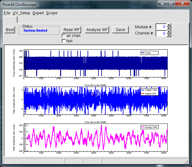
After the waveform has been acquired, it is possible to use the filter parameters to visualize the output of the filter. This is accomplished by pressing the "Analyze WF" button in the acquisition control panel." When that button is pressed, the main canvas is divided into three rows, the raw trace is displayed in the top row, the trigger filter in the second row, and the energy filter in the third row. Be aware that the filter results are merely calculated in nscope from the trace. They are not read from the device itself. However, they are produced in accordance with the description provided in the manual.
The most useful tool for visualizing the effect of parameters on the rate, the energy resolution, the effective energy threshold, and coincidence settings is the histogramming mode. Histogram acquisition mode is when a Pixie-16 card acquires data and histograms the energy internally. The state of the histogram for each channel can then be read out on demand. The user can then use the histogram to get a proper understanding of how the energy spectra will look without running Readout.
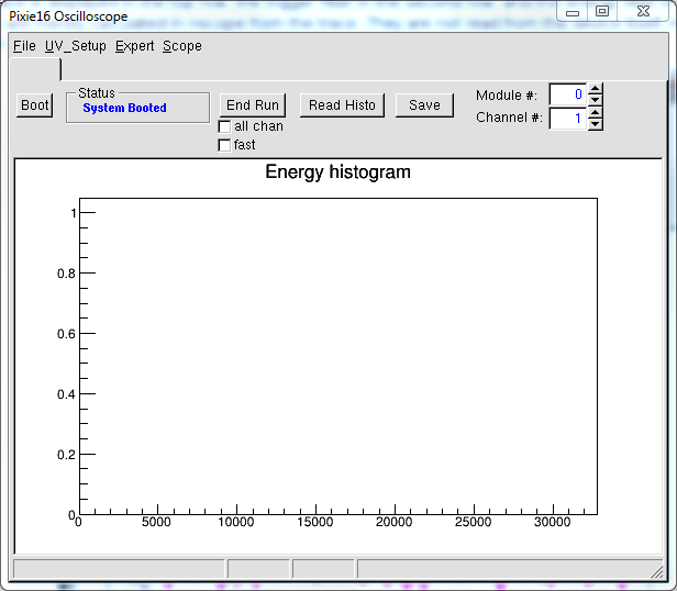
Histogram mode can be enabled by:
As a consequence of ending the run, the statistics for the device will be printed to the screen. An example of the output will be:
ending run in module 0
Run status 0 0
Run ended in module 0
Mod: 0 Chan: 0 input rate: 0 output rate: 0 livetime: 1
Mod: 0 Chan: 1 input rate: 0 output rate: 0 livetime: 1
Mod: 0 Chan: 2 input rate: 0 output rate: 0 livetime: 1
Mod: 0 Chan: 3 input rate: 0 output rate: 0 livetime: 1
Mod: 0 Chan: 4 input rate: 0 output rate: 0 livetime: 1
Mod: 0 Chan: 5 input rate: 0 output rate: 0 livetime: 1
Mod: 0 Chan: 6 input rate: 0 output rate: 0 livetime: 1
Mod: 0 Chan: 7 input rate: 0 output rate: 0 livetime: 1
Mod: 0 Chan: 8 input rate: 0 output rate: 0 livetime: 1
Mod: 0 Chan: 9 input rate: 0 output rate: 0 livetime: 1
Mod: 0 Chan: 10 input rate: 0 output rate: 0 livetime: 1
Mod: 0 Chan: 11 input rate: 0 output rate: 0 livetime: 1
Mod: 0 Chan: 12 input rate: 0 output rate: 0 livetime: 1
Mod: 0 Chan: 13 input rate: 0 output rate: 0 livetime: 1
Mod: 0 Chan: 14 input rate: 0 output rate: 0 livetime: 1
Mod: 0 Chan: 15 input rate: 0 output rate: 0 livetime: 1
Note that the input and output rates are listed along with the live time. The "input rate" pertains to the total number of fast triggers that were generated by the trigger definition. The "output rate" pertains to the total number of validated triggers. In other words, the output rate is the number of triggers that produced data to be read out.
The main canvas is just a standard ROOT canvas. If there are useful visualizations in it, it is possible to save it to file. The mechanism used for saving the file is the same as is provided by ROOT. The user can therefore save the canvas as a ROOT file, .jpg, .png, .pdf, .C, and other formats. To save the canvas:
Here are some common scenarios that have been encountered and how to fix them:
If after pressing the Boot button, the entire system froze and you see messages printed to the terminal that resemble the following:
Message from syslogd@spdaq22 at Mar 10 10:07:59 ...
 kernel:[  674.355937] NMI: PCI system error (SERR) for reason a1 on CPU 0.

Message from syslogd@spdaq22 at Mar 10 10:07:59 ...
 kernel:[  674.355941] Dazed and confused, but trying to continue
then there is a good chance that the clock distribution is not set up properly for the modules in the crate.
 1.8.1.2

